Sonocon B Portable Ultrasonic Flaw Detectors
Sonocon B Portable Ultrasonic Flaw Detectors
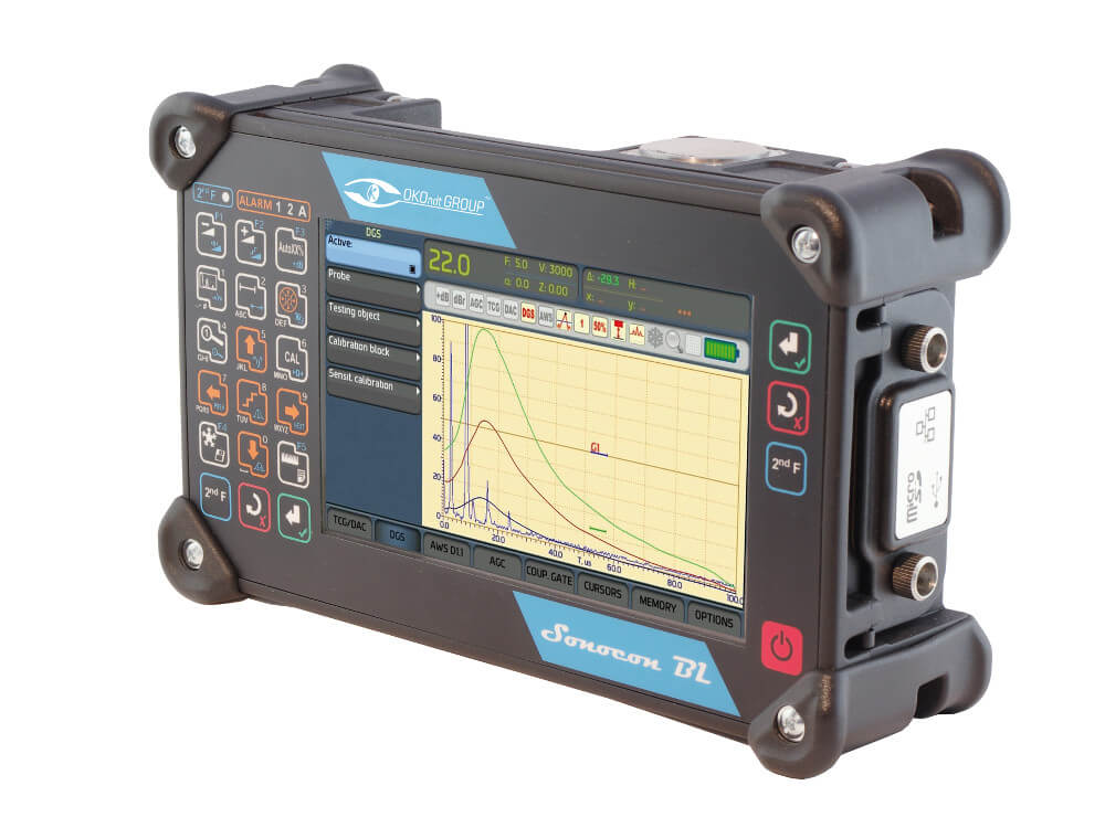
The Sonocon B belongs to the next generation of portable UT instruments. Using high-end electronics and having the richest set of modes and software features, it can solve any task that can be solved with a portable UT device.
Overview
-
Comfortable and Lightweight
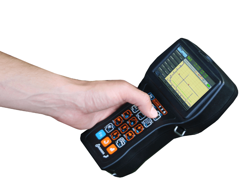
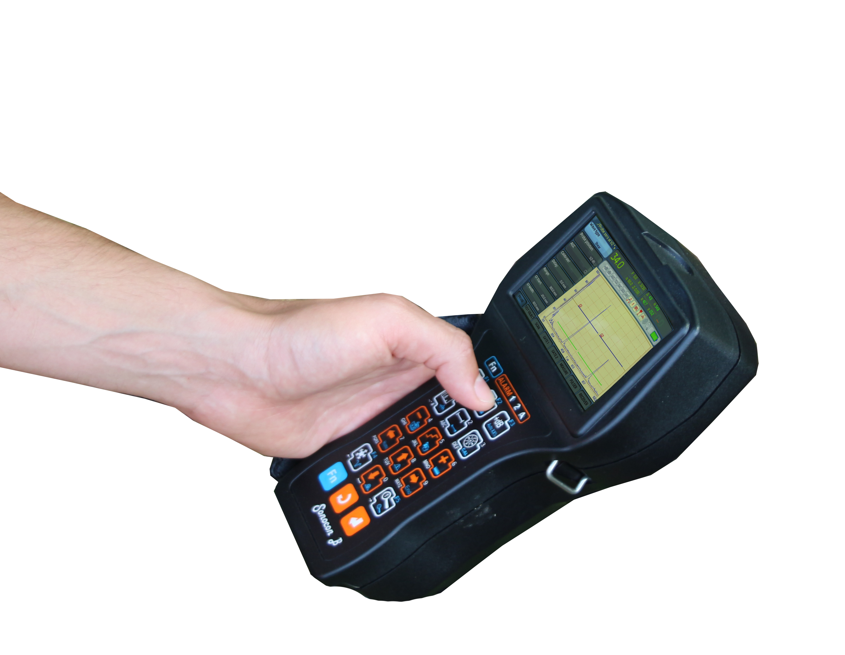
The Sonocon B is a lightweight inspection system – only 0.95 kg (2 lbs). Due to its ergonomic shape and a hand strap, it can be quite comfortably operated with a single hand, which is particularly important in the field and especially at height. It can be used by both left- and right-handers. A high contrast display of optimal size and resolution (800×480) prevents the operator’s excessive eyestrain.
-
Powerful and Multifunctional
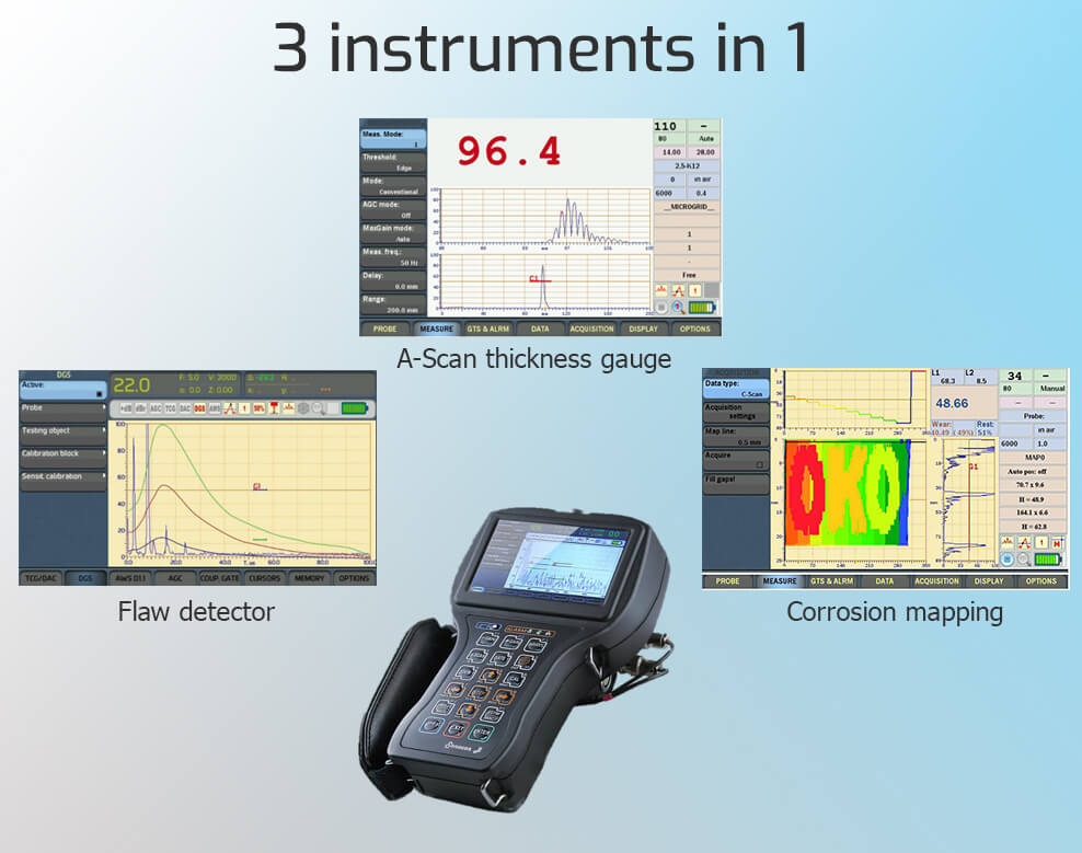
The Sonocon B is a digital UT tester combining 3 devices in 1:
- a flaw detector,
- an A-Scan thickness gauge,
- a corrosion monitor
This is realized with the help of switchable software. In the “UT” version, the Sonocon B fulfils all functions of a powerful ultrasonic flaw detector necessary for its setup, defect search and their advanced evaluation. In the “Thickness gauge +” version it turns into an advanced A-Scan thickness gauge, which also can do corrosion mapping.
-
Usage in Harsh Environments
High contrast display allows working in direct sunlight. The operation temperature range is from –30°C to +50 °C (-22°F to 122°F). The flaw detector is resistant to ionizing radiation impact and is intended for operation in increased humidity conditions.
-
Easy-to-Use
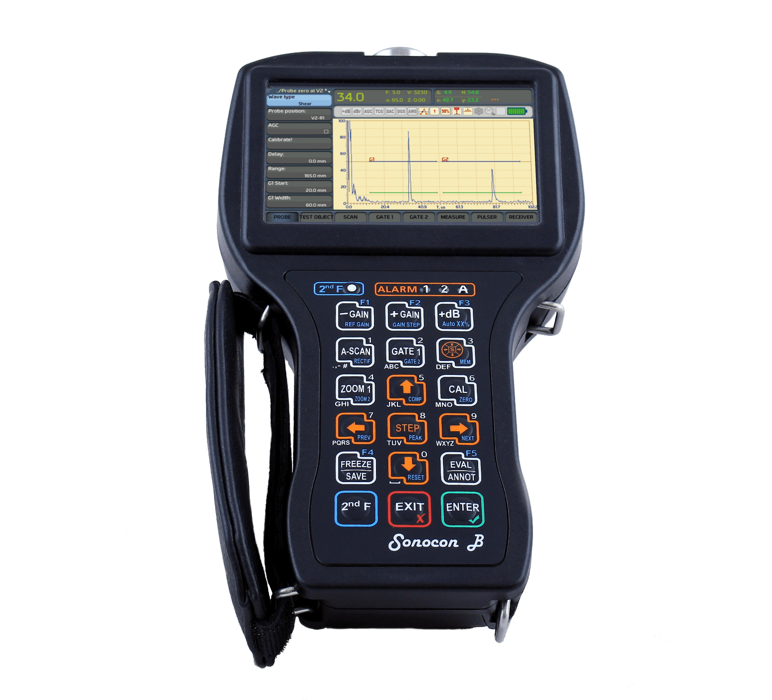
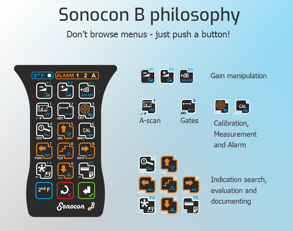
The Sonocon B is highly user-friendly. Its interface philosophy can be stated as “Don’t browse menus, just push a button!”. All most frequently used functions are placed on its keyboard making them accessible in a single or a couple of button presses. This makes setup and evaluation procedures several times faster. A variety of built-in auto calibration procedures allow to perform fast and easy calibration with straight beam, angle beam and Rayleigh wave probes on standards or even test pieces.
To help new users get to know its interface, the Sonocon B offers a number of options:
- Context backlight: In modes where a group of buttons is to be used, all relevant buttons are highlighted.
- Menu item hints: All not trivial menu items show descriptions when activated (changed).
-
Menu presets: A user can choose one of 3 menu system presets:
- Full: contains all menu items on 2 pages granting access to all UT instrument functions;
- Simple1 & Simple 2: contain all basic functions on one page, grouped in a couple of menus. It is also possible to add any 3 or 4 extra menus from a Full Menu List.
Industrial applications:
Testing of equipment, e.g. of the lifting mechanisms.
Testing of metal works etc.
Testing of the mill rolls.
Equipment testing.
Selective acceptance testing etc.
Aircraft parts testing: landing gear, wheels, flaps, engines, aircraft body components etc.
Testing of the welded joints of the railcar parts, locomotives, cisterns, bridges and so on.
Corrosion thickness gauging and mapping.
Wheelsets testing (wheels and axles).
Testing of casing pipes and metal structures of the rigs and platforms.
Pipelines testing.
Thickness gauging–corrosion search and mapping.
Testing of machines and mechanisms parts.
Equipment testing.
Selective acceptance testing of the machines parts.
Spot welding testing etc.
Testing of the welded joints of the pipelines, vessels, nozzles, power generation plant equipment.
Testing of machines and mechanisms parts.
Thickness gauging of turbine blades.
Thickness gauging–corrosion search and mapping, etc.
Testing of the welded joints of pipelines, vessels, nozzles, and other equipment.
Thickness gauging–corrosion search and mapping.
Testing of machines and mechanisms parts.
Now Sonocon available in two versions:
Software
General Features
Performance
Dual Mode Pulser
The Sonocon B implies two pulser modes: Spike Wave and Square Wave (SWP). This as well as a damping feature allow controlling echo shape, length and amplitude in wide ranges.
Waveform Averaging
This function permits averaging A-Scan from ×2 to ×64. This greatly raises Signal / Noise ratio, thus enabling comfortable operation at even very high gain and making measurements more precise.
Quick and Comfortable Operation
Direct A-Scan and Gate Control
After just pushing a single button, the operator can intuitively control A-Scan or gates.

Quick Access Menu
The QAM button grants access to a queue of circular menus which allow a quick change of measurement and alarm parameters.

"UT" Version
Indication Search and Evaluation Aids
“Legs Marking” Mode

The “Legs marking” mode changes A-Scan background by marking A-Scan parts corresponding to downgoing legs in yellow and to upgoing legs – in pink. This helps to visually estimate the depth of the reflector (defect) which causes an indication.
“Smart Zoom” Mode

In this mode, both zoomed A-Scan (from one of two gates) and a full unzoomed A-Scan are displayed. This prevents the operator from losing an off gate indication.
“Evaluate” Mode
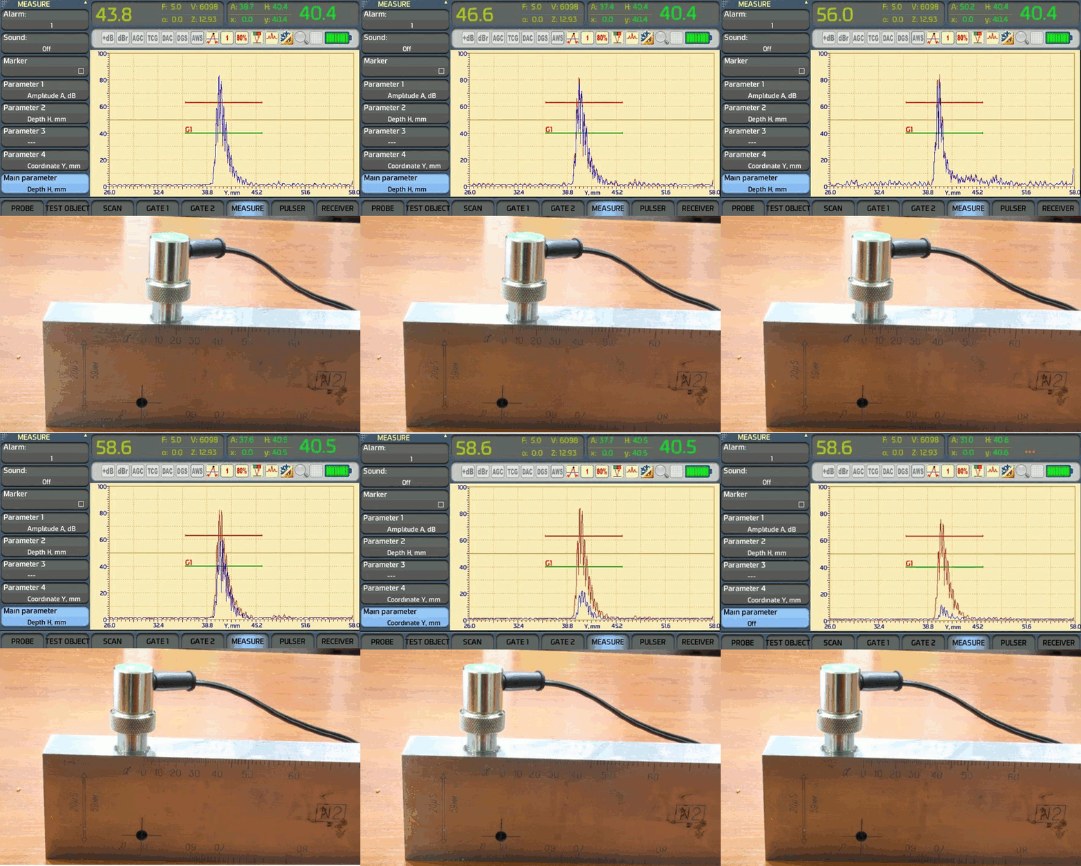
The “Evaluate” mode is very useful for evaluation of “hard to catch” indications. It also makes evaluation of usual indications much more quickly. When this mode is on, the operator needs only to make a blind scanning of the area of interest and the flaw detector will monitor all echoes in the 1st gate, find the best one (according to the amplitude), automatically adjust gain to put that echo to the evaluation level and freeze it. The “best” indication can be then evaluated and saved for reporting if needed. After the “Evaluate” mode is off, the scanning gain is automatically retrieved.
Flaw Evaluation Systems
DAC System

A built-in DAC system allows building DAC curves according to the following codes: ASME (single curve and 3 curves), EN 1712, EN 1713, EN1714, JIS Z3060, GB 11345, GB 4730. User presets are also available. Base curve can contain up to 128 points. Up to 6 additional curves can be built. Besides all standard functions used in any DAC system, the Sonocon B offers such advanced functions like “20-80” function, DAC ↔ TCG conversion function, etc.
DGS (AVG) System

The DGS system allows building up to 3 DGS curves for given equivalent diameters (area) for straight beam and angle beam single element transducers. It also gives direct readings of De and / or Se for gated indication.
AWS (D rating) System
The Sonocon B also employs the automated calculation of D-rating, according to American Welding Society Structural Welding Code, Section D1.1, D1.3.
"Thickness Guage +" Version
Setup Automation
Probe Library

To set up the selected probe parameters, it is enough to select a corresponding item from the Probe Library and all related settings will be loaded automatically.
Automatic Calibration

The Sonocon B offers a variety of automated calibration procedures: in air, on a built-in calibration block, and classical single and dual point calibration.
Result Storage and Processing
Structured Files

One of the most important and difficult tasks in thickness measurement with large test pieces is to correctly organize measurement results to facilitate their analysis. Using the Sonocon B, the operator can choose one of the several templates corresponding to almost any type of test piece:
- “Line” (1D) is ideal for small diameter pipes, etc.
- “Line+” (2D) is used for a linear group of “Line” objects, for section by section thickness measurement of large diameter pipes, etc.
- “Grid” (2D) is used for testing of large quasi planar object like ship hulls, storage tanks, large diameter oil storages, etc.
- “Line++” (3D) is used for testing of a 2D group of “Line” objects.
- “Grid+” (3D) is used for a linear group of “Grid” objects.
- “Boiler” (3D) organizes measurement points on pipes and pipes on levels.
On-the-Go Measurement Statistics

The Sonocon B allows not only reviewing organized measurement data, but also analyzing them, providing statistics for the whole file and each of measurement sites.
Corrosion Monitoring
Thickness B-Scans

The Thickness B-Scan, a section of the test piece produced by the ultrasonic beam, is easy to acquire with any 1D scanner with an encoder. It shows a back wall profile, which is useful for evaluating the corrosion type.
Thickness C-Scans

Thickness C-Scans are acquired with a 2D scanner or a series of linear scans with 1D scanner and are used for corrosion mapping.
PC Software
The Sonocon B goes with the PC software package corresponding to the inner software – UT, Thickness Gauge + or both.
C software is used for organizing instrument settings and testing results, testing result analysis and reporting.
Thickness Gauge +:

UT:

Specifications
General and "UT" Version
Setup Automation
Probe Library

To set up the selected probe parameters, it is enough to select a corresponding item from the Probe Library and all related settings will be loaded automatically.
Automatic Calibration

The Sonocon B offers a variety of automated calibration procedures: in air, on a built-in calibration block, and classical single and dual point calibration.
Result Storage and Processing
Structured Files

One of the most important and difficult tasks in thickness measurement with large test pieces is to correctly organize measurement results to facilitate their analysis. Using the Sonocon B, the operator can choose one of the several templates corresponding to almost any type of test piece:
- “Line” (1D) is ideal for small diameter pipes, etc.
- “Line+” (2D) is used for a linear group of “Line” objects, for section by section thickness measurement of large diameter pipes, etc.
- “Grid” (2D) is used for testing of large quasi planar object like ship hulls, storage tanks, large diameter oil storages, etc.
- “Line++” (3D) is used for testing of a 2D group of “Line” objects.
- “Grid+” (3D) is used for a linear group of “Grid” objects.
- “Boiler” (3D) organizes measurement points on pipes and pipes on levels.
On-the-Go Measurement Statistics

The Sonocon B allows not only reviewing organized measurement data, but also analyzing them, providing statistics for the whole file and each of measurement sites.
Corrosion Monitoring
Thickness B-Scans

The Thickness B-Scan, a section of the test piece produced by the ultrasonic beam, is easy to acquire with any 1D scanner with an encoder. It shows a back wall profile, which is useful for evaluating the corrosion type.
Thickness C-Scans

Thickness C-Scans are acquired with a 2D scanner or a series of linear scans with 1D scanner and are used for corrosion mapping.
PC Software
The Sonocon B goes with the PC software package corresponding to the inner software – UT, Thickness Gauge + or both.
C software is used for organizing instrument settings and testing results, testing result analysis and reporting.
Thickness Gauge +:

UT:

"Thickness Guage +" Version
| Pulser | |
| Type | Square Wave (SWP) |
| Autofit of the pulser parameters to the chosen probe | Voltage, Energy, Damping |
| Measurement frequency (readings refresh rate) | 1 to 100 Hz |
| PRF mode | Auto (Calculated from set readings refresh rate, accounting for averaging rate) |
| Receiver | |
| Range (at steel longitudinal wave) | 314 in (8 000 mm) |
| AGC | Individual to reach at 2 gates |
| AGC Modes | OFF / Edge / Peak |
| AGC Max Gain Modes | High, Medium, Low, Manual, Off |
| Auto filters choice (according to the probe type) | ✔ |
| Measurement | |
| Sound velocities range | .01 to .629 in/µs(250 to 16000 m/s ) |
| Measurement range | .016 to .629 in (0.4 to 16 000 mm) |
| Readings resolution | .001 / .01 / .1 in (0.01 / 0.1 / 1 mm) |
| Number of gates | 2 |
| Modes | 1, 1-2 |
| TOF Modes | Edge, Edge Zero Crossing |
| Units | mm / in |
| Min & Max capture mode | ✔ |
| Differential mode | ✔ |
| % of wear mode | ✔ |
| Temperature compensation | ✔ |
Acquisition of a:
|
✔ ✔ |
Measurements on the previously acquired:
|
✔ ✔ |
| Alarm & Display | |
| Alarm types | Min, Max, Min&Max |
| Coupling loss alarm | ✔ |
| Last reading (in coupling loss) | ✔ |
| A-Scan | ✔ |
| Cursor (Detect Line) | ✔ |
| Thickness B-Scan | ✔ |
| Thickness C-Scan | ✔ |
| Multidimensional files: Browsing | ✔ |
| Multidimensional files: File Statistics | ✔ |
| Multidimensional files Meas. Site Statistics | ✔ |
| Calibration | |
| 1-point | ✔ |
| 2-points | ✔ |
| Zeroing in the air | ✔ |
| Zeroing on a built-in block | ✔ |
| Memory | |
| Setups | ✔ |
| Multidimensional structured files | 1-3 dim |
| Number of readings per file | Up to 100 000 |
| Number of files format | 6 |
| Data attachments | Comments, A-Scans, Thickness B-Scans, Thickness C-Scans, Microgrids |
| Capacity | 2 GB (up to 64 GB) |
| PC software | ✔ |
| Other Features | |
| Keyboard backlight | ✔ |
| Smart (Context) keyboard backlight | ✔ |
| Smart zoom | ✔ |
| Number of keyboard shortcuts2 | 29 |
| 2 Number of instrument functions one can access with a couple of button presses. | |
-
Instructional Video
Introduction to Training
Part 1 Interface Concept
Part 2 Menu types
Part 3 Main functions
Part 4 Probe and test object parameters calibration
Part 5 DAC Calibration
